12 Foot Catboat

12 Foot Catboat
Designed by Edson Schock - Circa 1940's

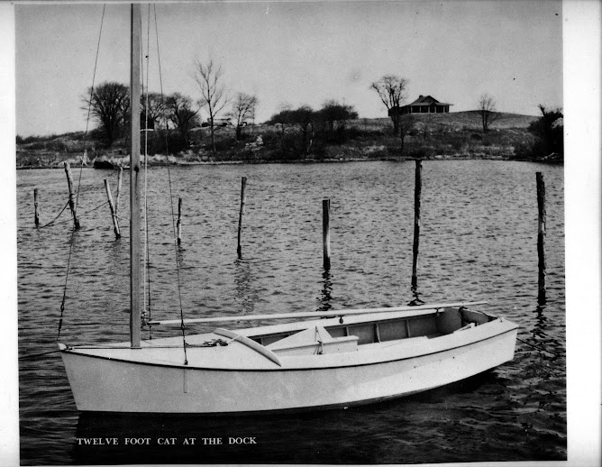
Follow me as I build a 12 foot catboat from plywood and pine. The boat was designed by Edson Schock in the 1940's. This is a project born of a desire to have another boat to sail here in Puerto Rico that will stand-up to the Trade winds. The sail plan will be changed to a gaff rigged sail. All the lumber is locally bought and pine will be substituted for oak, which is not readily available here. Marine plywood will be used.

Thursday, June 25, 2009

Shaping the keel

I began to work on the keel today. I laid out the batten along the keel slot and marked the position of each frame. I then transferred the frame locations to the keel board. I marked the width of the keel at each frame and laid a batten along these marks to make a curve for the keel shape.

[image]

[image]

I then took my saber saw and slowly cut the excess wood off from either end. A quick pass of the power planer squared and smoothed everything and it turned out great

Now I will wet it and, putting 2 blocks (cat is optional) in the middle, put some curvature into it to make it easier to set it into the boat.
[image]

Wednesday, June 24, 2009

Cutting the Keel

A simple but significant step today as I cut the board that I chose for the keel to its maximum width.

Next I will recheck all the frames and make sure they are plumb and fasten the bow stem into its final position.

When that is done, I will take a batten strip and mark the location of each frame. The batten will take the effects of curvature into account. I will mark the location of each frame on the keel board and lay out the taper of the keel.
[image]

Wednesday, June 3, 2009

Building the Foundation and Setting the Frames

Busy day today. The plan was to build the cradle or foundation, then square and level it. I had 2 14-foot 2x4’s for the sides and sliced a 2x4x8’ in two for the ends. The work went quickly and I figured why not start in on the setting the bow stem into position?

[image]
The foundation

After marking the center of the foundation at both ends, I cut two 1-foot 2x4’s and shimmed them to be level with the foundation and attached them with deck screws. Taking the bow stem and placing the 48” ruler to mark the forward most point for the stem, I took the angle of the stem from the full size drawing and set it correctly, making sure it was square and dead center to the foundation. A hefty 6” clamp will hold it in place.

[image]

That went pretty quick too so on to marking out the positions for the 10 frames and the transom. These were double-checked for accuracy by comparing measurements from the front and back of the foundation.

With this done I wanted to see if I could get a couple frames mounted. First, I had to run a mason line to use as a centerline. Measured it out and attached it then I put up frame number 1. I used a plumb bob to align it with the centerline then sank a couple deck screws into the spreader to hold it in place. 2 drills, one for pilot holes and the other as a driver, made quick work out of mounting the frames to the foundation.

[image]
3 frames done

[image]
5 done!

It went so quickly that I got all 10 and the transom set!

[image]

[image]

I am going to bevel the frames in place with an electric planer and we will see how that works!

Followers