12 Foot Catboat

12 Foot Catboat
Designed by Edson Schock - Circa 1940's

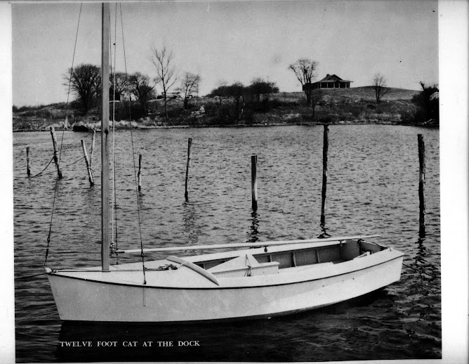
Follow me as I build a 12 foot catboat from plywood and pine. The boat was designed by Edson Schock in the 1940's. This is a project born of a desire to have another boat to sail here in Puerto Rico that will stand-up to the Trade winds. The sail plan will be changed to a gaff rigged sail. All the lumber is locally bought and pine will be substituted for oak, which is not readily available here. Marine plywood will be used.

Thursday, December 31, 2009

Bottom Panel Installed

Caulked, glued, screwed and nailed one of the bottom panels on the klast day of the year. Terri brushes off the finished product after helping me apply the glue, feeding me screws and nailing the back half of the panel down. This one was a bit easier on the back as there was no bending upside down to nail like we had to do with the sides.

[image]

The next step will be to fit the template to the other side and prepare to cut the other panel out.


[image]

All in all the installation went great and we can see the day coming that we will be able to turn her over and start working on the top of the boat!
Monday, December 28, 2009

1st Bottom Panel

Today, we finished adjusting the pattern for the bottom panel, Things went so well (thanks to Terri's help) that we cut the 1st bottom panel out and made some minor adjustments to make sue it met the keel properly.

[image]

There is still a lot to do. Tomorrow, we will begin to lay out where the frames are so we can drill pilot holes for the screws and nails.

The panel sits nicely and is another big accomplishment towards finishing her!

[image]

Thursday, December 24, 2009

The Skeg

Got the skeg attached today. It went easy and it will get another piece attached over the end and up the transom to give it additional rigidity.

[image]

Tuesday, December 22, 2009

2nd Side Panel Installed

Today we were able to get the other side panel install and it went very quick and smoothly. The frame is real rigid now and we will start working on installing a skeg to the keel.

[image]

Saturday, December 12, 2009

Side Pattern

We got back to work today. We done some smaller tasks in the meanwhile but today we were ready to make a pattern for the side panels.

Marine plywood costs almost $200 for a 12 foot sheet so we bought a $10/sheet panel of Luann plywood, like they use on a door to make sure we got the cutting right.

The pictures show the pattern in place. Tomorrow we will staple a piece at the joint to keep it together then get a sheet of marine plywood on Monday or Tuesday.

[image]

[image]

Friday, October 9, 2009

2nd Chine Strip

Put the 2nd of 4 strips in to the frames to give the entire frame assembly stiffness and have a place to land and anchor the plywood sides and bottom pieces.

[image]
[image]
[image]

The next 2 strips will be about the same but now that I have a "system" for installing them, it should go fairly easy!

Sunday, October 4, 2009

Setting the 1st Chine Strip

Some jobs are not very large but present their own set of unique challenges. The setting of the strips is a difficult job mostly for the complexity of the angles where the strips meets the stem or front of the boat. It took 2 cuts and a bit of fine tuning but I managed to get it fastened into the stem, as well as frames 1 & 2!

[image]

[image]

Monday, September 7, 2009

Resetting the 1/2 Frames

Prior to making the centerboard box, I removed 3 frames, #5,6 & 7, to make room to take the keel contour and fabricate the centerboard box. With the CB Box back in place, it was time to cut 4-3/4" from the center of these frames.

[image]

I then set each frame back in its place, having had marked their orinal positions on the keel and foundation, starting with #5.

[image]

[image]
In goes #6

[image]

Finally they are all back in. There are 1-1/2 x 3" blocks on top of the keel that I will install next to where each frame meets the CB Box. They will be glued and screwed into the 2 x 6 bedlog then I will glue and crew each frame into them for additional support. There are 6 to install. 2 on each frame. I cut 12 by mistake!

Setting the Centerboard Box on the Keel

Today was a big event, placing the centerboard into the slot and making it permanent.

I began by drilling the holes for the bolts that will hold the box to the keel.

[image]

[image]

[image]

Sunday, August 30, 2009

Assembling the Centerboard Box

My hardware arrived today and I want to get teh centerboard box in place asap. I glued, screwed and bolted the centerboard box together this afternoon so I can prepare to mount it tomorrow.

[image]

[image]

Wednesday, August 26, 2009

Painting the Inside of the CB Box

With the headledges screwed and glued in place, it is time ti get the inside of the CB Box painted before I assemble the 2 sides together.

I am using an Anti-fouling paint that contains Cuprous oxide or copper powder suspended in the paint. It is a heavy can and the copper will discourage marine life from growing onto a surface, copper being toxic to most living things.

[image]

The paint requires almost constant stirring to ensure the copper remains suspended in the paint.

It goes on thick and I have taped off the area where the other headledge gets glued so that the surface remains clean.

[image]

[image]

Attaching the headledges

Another glue and screw operation.

[image]

Attaching the Sides to the Bedlogs

I began gluing and screwing parts of the centerboard box today. I went slowly to get it right. I piloted holes for some 16 or so silicone bronze wood screws tro hold the side panels and bedlogs together.

I understand tat you should no countersink plywood but there are times when it cannot be avoided and this is one of those times.


[image]

I mixed a batch of glue, slathered it on to the 2x6 and waxed the screws, sinking them by hand with the bit brace.

[image]

It turned out right and tomorrow I will do the other side!

[image]

Thursday, August 20, 2009

Shaping the Centerboard Box

I love power planers! What a time saver it was. In a half hour, I trimmed her down to the lines that I took off the keel curvature.

[image]

I had about 1-1/2" to remove in the forward part and 3/4" of wood to removed in the back and what would have taken me at least 4 hours was accomplished in 30 minutes!

[image]

Gotta love it!

Wednesday, August 19, 2009

Assembling the Centerboard Box

I cut 2 pieces of marine plywood and cut 2 pieces of 2 x 6 and added two 1 x 2-1/2" pieces of pine to form the centerboard box. The 1 x 2-1/2" pine go on either end to provide a space to fit the pivoting centerboard in.

[image]
The plywood panels assembled with the pine end pieces.

[image]
Cutting the 2 x 6's

After checking for the initial fit of the pine board to the plywood, I added the 2 x 6's to the form to complete the mock up for fitting into the slot I had cut into the keel.

[image]

I had already removed frames 5, 6 & 7 in order to be able to lift and place the keel box. I had chiseled and rasped the openings to widen and square them a little more to get the right fit.

[image]

Placing my hydraulic lift under the center of the box, I lifted it into position, plumb with the face of frame #4.

[image]

This is not the final position but serves to illustrate the concept about how I will now transfer a parallel curved line of the keel to the sides of the 2 x 6's to allow a nice watertight fit against the keel. I will shave that down with the power planer.

More on that in the next installment!

Thursday, August 6, 2009

Cutting the Centerboard Slot

The centerboard is lowered when the sail is raised. It is a piece of wood that project 2-3 feet below the bottom of the boat and is there to resist the force of the wind from pushing the boat sideways. Sort of like the tail on an airplane, it helps track the boat forward.

I have made a 3/4" wide opening along the center line of the keel. This will be the first step in the construction of a "box" to contain it when it is in an upright position.

It was a fairly easy operation. Drawing the limits out in pencil, I plunged my circular saw into the wood and cut it from one end to the other.

[image]

I finished the cut with my hand saw then used my saber saw to cut the ends.

[image]

[image]

Thursday, June 25, 2009

Shaping the keel

I began to work on the keel today. I laid out the batten along the keel slot and marked the position of each frame. I then transferred the frame locations to the keel board. I marked the width of the keel at each frame and laid a batten along these marks to make a curve for the keel shape.

[image]

[image]

I then took my saber saw and slowly cut the excess wood off from either end. A quick pass of the power planer squared and smoothed everything and it turned out great

Now I will wet it and, putting 2 blocks (cat is optional) in the middle, put some curvature into it to make it easier to set it into the boat.

[image]

Wednesday, June 24, 2009

Cutting the Keel

A simple but significant step today as I cut the board that I chose for the keel to its maximum width.

Next I will recheck all the frames and make sure they are plumb and fasten the bow stem into its final position.

When that is done, I will take a batten strip and mark the location of each frame. The batten will take the effects of curvature into account. I will mark the location of each frame on the keel board and lay out the taper of the keel.
[image]

Wednesday, June 3, 2009

Building the Foundation and Setting the Frames

Busy day today. The plan was to build the cradle or foundation, then square and level it. I had 2 14-foot 2x4’s for the sides and sliced a 2x4x8’ in two for the ends. The work went quickly and I figured why not start in on the setting the bow stem into position?

[image]
The foundation

After marking the center of the foundation at both ends, I cut two 1-foot 2x4’s and shimmed them to be level with the foundation and attached them with deck screws. Taking the bow stem and placing the 48” ruler to mark the forward most point for the stem, I took the angle of the stem from the full size drawing and set it correctly, making sure it was square and dead center to the foundation. A hefty 6” clamp will hold it in place.

[image]

That went pretty quick too so on to marking out the positions for the 10 frames and the transom. These were double-checked for accuracy by comparing measurements from the front and back of the foundation.

With this done I wanted to see if I could get a couple frames mounted. First, I had to run a mason line to use as a centerline. Measured it out and attached it then I put up frame number 1. I used a plumb bob to align it with the centerline then sank a couple deck screws into the spreader to hold it in place. 2 drills, one for pilot holes and the other as a driver, made quick work out of mounting the frames to the foundation.

[image]
3 frames done

[image]
5 done!

It went so quickly that I got all 10 and the transom set!

[image]

[image]

I am going to bevel the frames in place with an electric planer and we will see how that works!

Friday, May 29, 2009

Gluing and Nailing the Transom Together

I glued and nailed the transom today. I originally was going to use screws but decided to go with nails once I realized that I would have to go through the plywood and into the frame in order to get a better “bite” for the nails. Going through the frame wood and then into the plywood gave me only a ¼” depth on a 1” nail or screw and I only had a total thickness of 1-1/4” so anything longer than a 1” nail was out if the question.

Going through he plywood first poses its own minor problems. I have to align all the frame pieces using the outside edges exclusively so I will need to be careful about keeping the frame stable while I prepare it with pilot holes for the nails and keep them aligned with some temporary small nails like I used on the gussets.

I pilot drilled one section at a time, putting an alignment nail in every couple holes.

[image]

That completed, it was time to mix a batch of Weldwood Resin Glue and apply it to the inside of the frames. It was very warm today so the thin layer would dry quickly and I had to quickly reassemble the plywood to the frame pieces and get at least a couple nails in each frame piece to prevent them from moving. I was a bit frantic but my hammer drove the nails home quickly.

[image]

The finished result looked great!

[image]

I spent the rest of the afternoon carefully laying out the cut lines for the stringers and the keel.

Followers