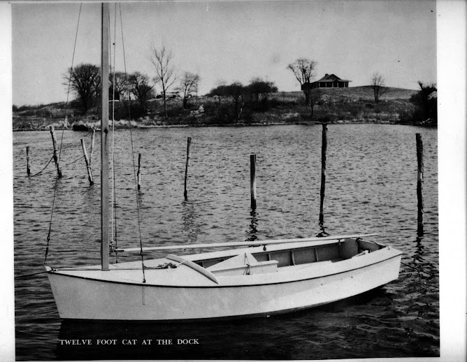
12 Foot Catboat

12 Foot Catboat
Designed by Edson Schock - Circa 1940's

Follow me as I build a 12 foot catboat from plywood and pine. The boat was designed by Edson Schock in the 1940's. This is a project born of a desire to have another boat to sail here in Puerto Rico that will stand-up to the Trade winds. The sail plan will be changed to a gaff rigged sail. All the lumber is locally bought and pine will be substituted for oak, which is not readily available here. Marine plywood will be used.

Thursday, June 25, 2009

Shaping the keel

I began to work on the keel today. I laid out the batten along the keel slot and marked the position of each frame. I then transferred the frame locations to the keel board. I marked the width of the keel at each frame and laid a batten along these marks to make a curve for the keel shape.

[image]

[image]

I then took my saber saw and slowly cut the excess wood off from either end. A quick pass of the power planer squared and smoothed everything and it turned out great

Now I will wet it and, putting 2 blocks (cat is optional) in the middle, put some curvature into it to make it easier to set it into the boat.

[image]

Wednesday, June 24, 2009

Cutting the Keel

A simple but significant step today as I cut the board that I chose for the keel to its maximum width.

Next I will recheck all the frames and make sure they are plumb and fasten the bow stem into its final position.

When that is done, I will take a batten strip and mark the location of each frame. The batten will take the effects of curvature into account. I will mark the location of each frame on the keel board and lay out the taper of the keel.
[image]

Wednesday, June 3, 2009

Building the Foundation and Setting the Frames

Busy day today. The plan was to build the cradle or foundation, then square and level it. I had 2 14-foot 2x4’s for the sides and sliced a 2x4x8’ in two for the ends. The work went quickly and I figured why not start in on the setting the bow stem into position?

[image]
The foundation

After marking the center of the foundation at both ends, I cut two 1-foot 2x4’s and shimmed them to be level with the foundation and attached them with deck screws. Taking the bow stem and placing the 48” ruler to mark the forward most point for the stem, I took the angle of the stem from the full size drawing and set it correctly, making sure it was square and dead center to the foundation. A hefty 6” clamp will hold it in place.

[image]

That went pretty quick too so on to marking out the positions for the 10 frames and the transom. These were double-checked for accuracy by comparing measurements from the front and back of the foundation.

With this done I wanted to see if I could get a couple frames mounted. First, I had to run a mason line to use as a centerline. Measured it out and attached it then I put up frame number 1. I used a plumb bob to align it with the centerline then sank a couple deck screws into the spreader to hold it in place. 2 drills, one for pilot holes and the other as a driver, made quick work out of mounting the frames to the foundation.

[image]
3 frames done

[image]
5 done!

It went so quickly that I got all 10 and the transom set!

[image]

[image]

I am going to bevel the frames in place with an electric planer and we will see how that works!

Friday, May 29, 2009

Gluing and Nailing the Transom Together

I glued and nailed the transom today. I originally was going to use screws but decided to go with nails once I realized that I would have to go through the plywood and into the frame in order to get a better “bite” for the nails. Going through the frame wood and then into the plywood gave me only a ¼” depth on a 1” nail or screw and I only had a total thickness of 1-1/4” so anything longer than a 1” nail was out if the question.

Going through he plywood first poses its own minor problems. I have to align all the frame pieces using the outside edges exclusively so I will need to be careful about keeping the frame stable while I prepare it with pilot holes for the nails and keep them aligned with some temporary small nails like I used on the gussets.

I pilot drilled one section at a time, putting an alignment nail in every couple holes.

I glued and nailed the transom today. I originally was going to use screws but decided to go with nails once I realized that I would have to go through the plywood and into the frame in order to get a better “bite” for the nails. Going through the frame wood and then into the plywood gave me only a ¼” depth on a 1” nail or screw and I only had a total thickness of 1-1/4” so anything longer than a 1” nail was out if the question.

Going through he plywood first poses its own minor problems. I have to align all the frame pieces using the outside edges exclusively so I will need to be careful about keeping the frame stable while I prepare it with pilot holes for the nails and keep them aligned with some temporary small nails like I used on the gussets.

I pilot drilled one section at a time, putting an alignment nail in every couple holes.

[image]

That completed, it was time to mix a batch of Weldwood Resin Glue and apply it to the inside of the frames. It was very warm today so the thin layer would dry quickly and I had to quickly reassemble the plywood to the frame pieces and get at least a couple nails in each frame piece to prevent them from moving. I was a bit frantic but my hammer drove the nails home quickly.

[image]

The finished result looked great!

[image]

I spent the rest of the afternoon carefully laying out the cut lines for the stringers and the keel.

Thursday, May 28, 2009

Making the Transom

The final "frame" is the transom or back end of the boat. It must be strong because the sides and bottom panels end here.

I am using 1/2" marine plywood plus the 1" (3/4", really) pine to make it and it will be reinforced to add to its strength. It will have more screws that nails when I go to put it together.

The most important part is to make a pattern for what is called the "deck crown". This is a curve that runs from side to side and then, in the middle, there is a rise to allow for water run-off. At the widest part of the boat, Frame #6, the width is 72" and the amount of rise between the outside edge of the boat and the middle of the deck was 2-1/2 inches according to the drawing. When I laid it out on the transom, it was way too radical of a rise so I decided to reduce it to 1-1/2" over 72". This gave a more gradual curve and is enough for any water to roll off easily.

There is a formula for figuring the rise that I pulled from an old boat building book. I cut out a 2" x 75 inch piece of Luann plywood then marked its center. I then drew an arc of 1-1/2". Divided the bottom line of the arc into 4 even pieces and then divided the arc curve into 4 even spaces. This will tell me the rise of the curve at 12, 24 and 36 inches from the center of the template.

[image]

I cut the curve into the template with my saber saw and drew it on to the plywood that I cut out the day before to make the transom.

[image]

I cut the curve out.

[image]

[image]

I wanted to add a piece of wood across the top of the transom for further reinforcement so, I laid it out and fitted it to the top.

[image]

I will add one more piece of pine to the center then glue and screw it all together.

Wednesday, May 27, 2009

Bow Stem Final Cuts

I wanted to see if I could get the bow stem cut to its final size. I measured the bevels, set the table saw blade to the correct angle and hoped that I would get it right. I discovered that you cannot easily transfer lines over an irregularly shaped surface and the blade angle did not align with my drawn-on lines. The solution is to go with the saw blade angle which was taken directly from the full size drawing. The worked just fine. After cutting a test cut, I compared it to the actual line drawing and it matched exactly. Cut the bottom then notched out 3/4" of the back part of the stem to receive the keel. Measured the angle of the top cut and make the cut. Perfect!

[image]
Before the cut

[image]
Ready to install!

Monday, May 25, 2009

The Bow Stem

At the very front of the boat is the bow stem or cut water, as it is sometimes called. This is always a challenge for me because math was never my strongest suit. I took the clearest 2 x 4 I could find and sawed it into 2 - two foot pieces. I measured the angle that the side would be as it came in to meet the bow stem and set up the table saw. The 2 - four foot pieces go back to back so that one receives the plywood and the other covers the end of the plywood and projects out forward of it to the very front of the boat. They get cut at the same angle.

[image]

Everything having been cut correctly (supposedly!) I now join them with glue and wood screws.

[image]

This will dry overnight and I will cut it down to the correct size soon.

Saturday, May 23, 2009

Cutting the Keel Slot

I have completed cutting the last step on all the frames, cutting a slot to accept the keel. This takes time to make sure it is done correctly. I decided a depth of 1/2" would be the best to get the landing area I need for the bottom panel. I wanted about an inch and a half so I would get good adhesion and lots on wood for the screws and nails that will hold the bottom panel in place. But that comes later. I laid out the slot to a depth of 1/2" on the face face. The face is the side that does not have the gussets or floor pieces mounted, just a clean side that is aligned with the position marks laid out on the drawing. The keel will always be 1/2" deep on this side of the frame.


Next, I transfer the lines across the top of the frame to the other side.


Now I measure the depth of the curvature 1-1/2", to allow for the 2 - 3/4" thicknesses of the frame wood and determine how much deeper I need to cut the slot at that point to allow for the curvature. In some places, I needed to add 5/16" to the 1/2" to allow for the curvature.


Now I used a hand saw to cut the depth of the slot to the limit lines on both sides of the frame and then used a chisel to remove the excess. I will fine tune the slot with a wood rasp.


Friday, May 8, 2009

Stringer cuts

I have been advancing by leaps and bounds until I hit the cutting of the frames. Here I get bogged down in making cuts into the frame that will accept the long stringers that will help reinforce the framing. I isn’t a simple matter of notching out a ¾ x 1-1/2” hole. At each frame there are two angles that must be taken into consideration in order for the stringer to sit properly against the frame. The angles are more pronounced as I approach the bow, where the more radical angles are located.

For example, I need first to determine the depth and angle of the cut that will be 1-1/2” deep.


The next cut also has an angle that must be included in order to complete the cut. The angle lines represent the bevel on this frame. The bevel is an area of wood that will be planed off to allow the bottom or side plywood panel to sit flat against the frame.


The roughed-out result looks like this:


Both sides of the frame also receive a long stringer. This one will represent the deck level and also requires angled cuts.


These are just the rough-cuts and will be refined to get a good contact and proper depth.

This takes time and thought as there 48 of them to do. I am completing 2 frames a day, as time allows and taking my time. After this is done, I will make the cut-out on each frame for the keel. This will be a wider cut in the center of each frame.

Thursday, May 7, 2009

Floors and Spreaders

I began to glue and nail the floors to the frames yesterday and finished them this morning. Stacked against themselves, you can get an idea of what the contour of the boat will look like.


With the floors all installed, it was time to install the spreader. The spreader is a 1-1/2" x 1-1/2" piece that gets installed where the frame gets set onto the "foundation" or building cradle. It adds support to the frame during construction and locates the frame at the correct height on the foundation.

The building cradle will be a rectangle 14 feet long by 4 feet wide. Squared and leveled, the cradle will support the boat as it gets built. It is one of the next things that gets built.

Back to the spreaders.

I cut each spreader at least 4 feey wide and more as the frames widen. I think the widest was around 78 inches.

I pilot each spreader then attach it in the correct position with decking screws.


Every screw, no matter its function, gets waxed before screwing it in to lubricate it.

The finished products:


Tomorrow, I will either start the cradle or cut the insets for the long wood stringers that will help hold the frames in place.

Followers